

FROM DESIGN TO MANUFACTURING
What Is CAD/CAM?
A connected workflow that takes a part from computer-aided design through machining simulation to a CNC program.
What do CAD and CAM mean?
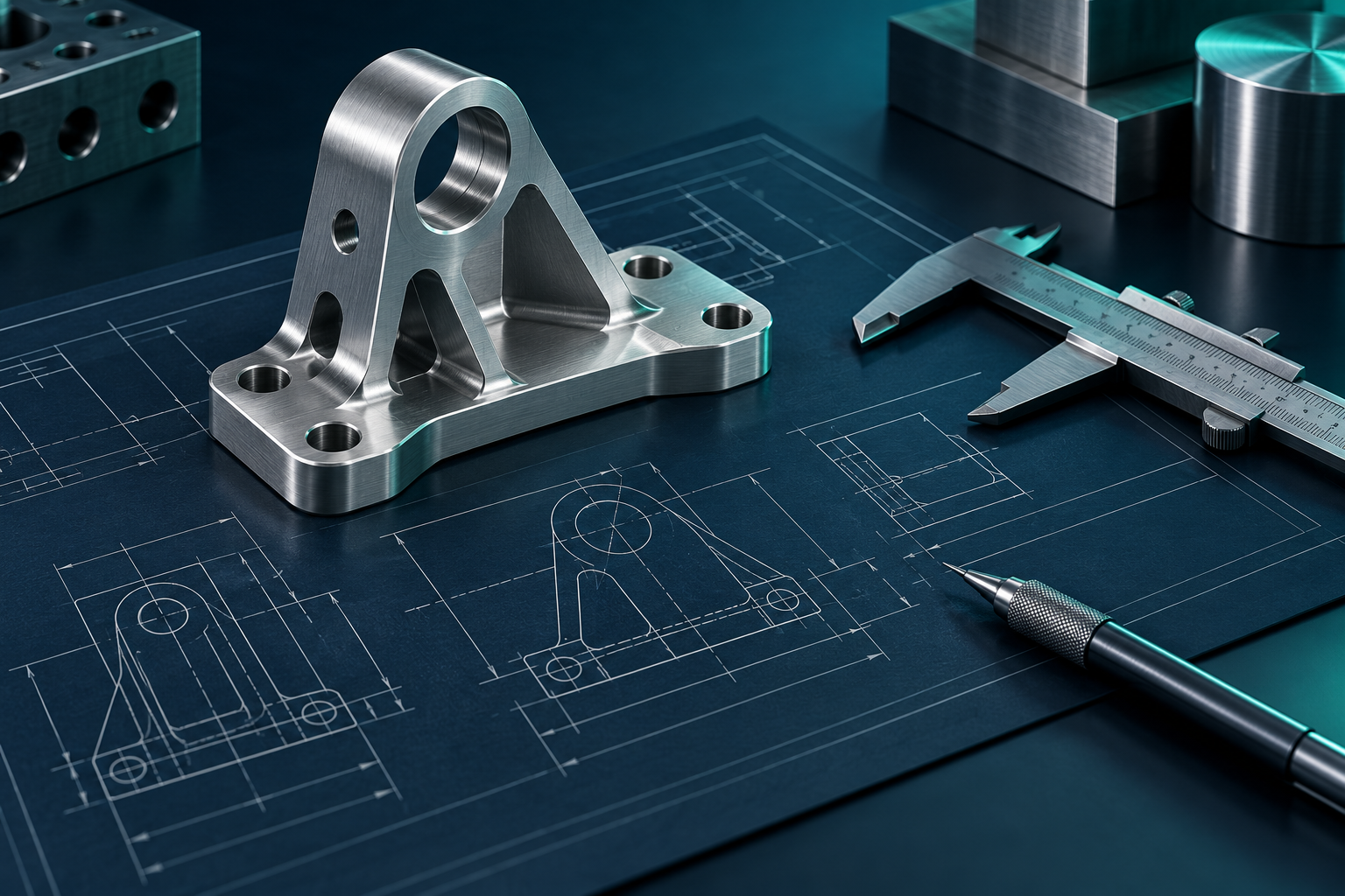
CAD (Computer-Aided Design) is the preparation of 2D drawings and 3D models for a product or mould. Dimensions, geometry and design revisions are managed digitally. In mould manufacturing, components such as cores, cavities, runners, cooling channels and electrodes can be reviewed within the same design data.
CAM (Computer-Aided Manufacturing) turns CAD geometry into manufacturing operations. It creates toolpaths based on the tool, stock, setup and cutting parameters. Simulation helps review operation order, remaining material and possible collisions. A selected postprocessor converts toolpaths into NC/G-code suited to the CNC control.
A typical CAD/CAM workflow
- Create the part or mould model and drawing; verify dimensions and geometry.
- Define stock, workholding, machine, tools and machining allowances.
- Choose operations and generate toolpaths for roughing, rest machining and finishing.
- Use simulation to review material removal, tool motion and possible collisions.
- Generate NC code with the postprocessor for the machine and control; verify it for the actual setup.
Manufacturing benefits and checks
A well-configured CAD/CAM workflow makes design data reusable, shortens programming time and helps reveal machining issues earlier. For moulds and precision parts, it creates a more consistent link between the model, toolpath, simulation and manufacturing records.
The result depends on model accuracy, stock and setup definitions, tool geometry, cutting parameters and postprocessor settings. Always verify generated NC code against the machine control, work offset and safety conditions.
Every step from model to CNC code should be evaluated against the actual machine and tooling conditions.